

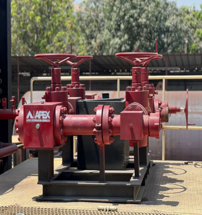
Chokes are throttling valves that allow operators to control the wellstream. They are capable of withstanding erosion resulting from the very high velocities occurring at and immediately downstream from the orifice.
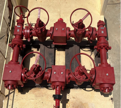
The Apex Choke Manifold allows operators to limit erosion to the replaceable parts within the choke. The standard Apex Choke Manifold is a five-valve, component design with a full-bore flow path through the manifold, allowing total bypass of the choke control. On one side of the bypass, an adjustable choke allows more flexible control for wellbore cleanup rates. On the other side is a positive choke to give more accurate flow control for predetermined fluids for various test procedures. By using the valving and adjustable choke, the operator can change the positive choke without having to stop operations or affect test objectives.
Features and Benefits
- Features dual chokes, one adjustable and one positive, to help maintain a constant flow rate, which improves test data quality.
- Designed for easy maintenance during operations, saving rig time and overall test cost.
- Offers a lower overall redress cost because of its component design.
- Allows more options during cleanup with its bypass through the manifold.
- Meets applicable industry standards (API 6A) and can be third-party certified as required.
Operation
The choke allows the operator control by enabling progressive manual, powered, or fixed control of the wellstream by opening, closing, or selecting an orifice. Chokes help maintain critical flow, even while changing choke size.
Critical flow occurs when the pressure downstream of the choke is one-half or less than the pressure upstream. In this case, the flow rate through the choke depends only on variations of the upstream pressure and on choke setting. Changes in downstream pressure within the critical flow range do not affect the rate of flow through the choke.
Non-critical flow occurs when the downstream pressure is more than one-half the upstream pressure. In this case, changing the pressure will affect the flow rate through the choke. The critical flow should always be maintained across the chokes. The choke manifold should be placed as close as possible to the production equipment.
Choke Manifold Specifications
| Working Pressure psi (kPa) | 5,000 (34,475) | 10,000 (68,950) | 15,000 (103,425) | 15,000 (103,425) |
|---|---|---|---|---|
| Service | H2S* | H2S* | H2S* | H2S* |
| Chokes | Cameron Type H2 3 1/8 5,000 2-in. max. orifice one adjustable one positive | Cameron Type H2 3 1/16 10,000 2-in. max. orifice one adjustable one positive | Cameron Type H2 2 9/16 15,000 2-in. max. orifice one adjustable one positive | Cameron Type H2 3 1/16 15,000 2-in. max. orifice one adjustable one positive |
| Valves | Cameron Type FC 3 1/8-in. 5,000 | Cameron Type FC 3 1/16-in. 10,000 | Cameron Type FC 2 9/16-in. 15,000 | Cameron Type FC 3 1/16-in. 15,000 |
| Flanges | 3 1/8 API 6 Bx 5,000 | 3 1/16 API 6 Bx | 2 9/16 API 6 Bx | 3 1/16 API 6 Bx |
| Studs | A320 GR L7 NACE Class II | A320 GR L7 NACE Class II | A320 GR L7 NACE Class II | A320 GR L7 NACE Class II |
| Tee | with fluid cushion target | with fluid cushion target | with fluid cushion target | with fluid cushion target |
| Crossovers | 3 1/8 API 6 Bx Weco Fig 1002 Union one wing half one thread half with ported blank plug -20°F (-29°C) | 3 1/16 API 6 Bx Weco Fig 1502 Union one wing half one thread half with ported blank plug | 2 9/16 API 6 Bx Weco Fig 2202 Union one wing half one thread half with ported blank plug | 3 1/16 API 6 Bx Weco Fig 2202 Union one wing half one thread half with ported blank plug |
| Operating Temperatures | ambient to 350°F (176°C) maximum fluid temperature | -20°F (-29°C) ambient to 350°F (176°C) maximum fluid temperature | -20°F (-29°C) ambient to 350°F (176°C) maximum fluid temperature | -20°F (-29°C) ambient to 350°F (176°C) maximum fluid temperature |
| Skid Length in. (cm) | 102 (259.08) | 102 (259.08) | 96 (243.84) | 102 (259.08) |
| Skid Width in. (cm) | 72 (182.88) | 73 (185.42) | 72 (182.88) | 73 (185.42) |
| Skid Height in. (cm) | 41 (104.14) | 41 (104.14) | 39 (99.06) | 45 (114.3) |
| Skid Weight lb. (kg) | 5,200 (2359) | 5,600 (2540) | 5,700 (2586) | 6,500 (2948) |
Meets requirements of NACE MR-01-75
NOTE: Other sizes, configurations, and pressure ratings are available to meet most applications. These ratings are guidelines only. For more information, contact your local Apex representative.