
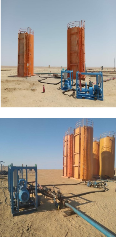
The tank is designed to allow easy access for multiple valves forming the inlet and outlet manifold. This optimizes use of the tank for clean-up operations or to store liquids.
A flame arrestor is an integral feature of the tank and is located at the gas/vent outlet line at the top of the tank. An additional safety feature is the inclusion of vent hatches/manholes, created by forming a balanced man entry opening, which allows the cover to be lifted, thus venting to the atmosphere should pressure begin to build up in the vessel.
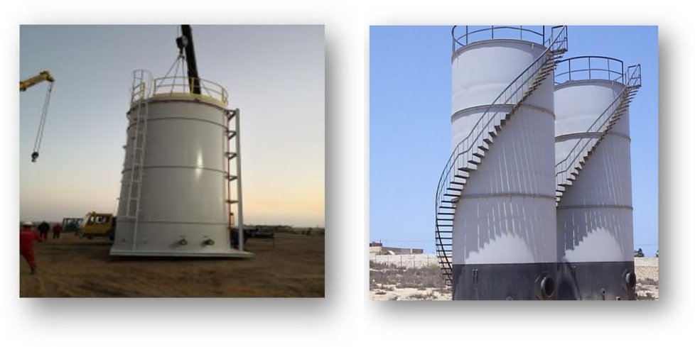
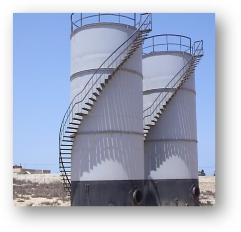
The tank is equipped with internal access by a permanently installed ladder and foldable top handrails to ensure operator safety. Tanks may also be equipped with steam coils to provide the necessary heat required to ensure fluid viscosity is retained during operations.
The high capacity of the tank is an additional benefit for operations where well production can be transported to a loading facility, and the crude can be transferred for further processing.
Features and Benefits:
- Allows safe crude transfer for additional processing
- Foldable roof top handrail
- External and Internal ladder
- Detonation Flame arrestor
- Thief Hatch
- Liquid Level indication
- Vacuum relief device to prevent overpressure
- Earthing System
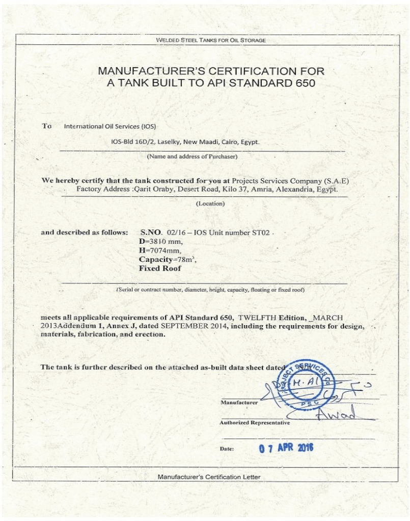
Technical Specifications
| Capacity | 500 / 1000 bbls |
|---|---|
| Working Pressure | 14.73 Psi (Atmospheric) |
| Temperature range (°F / °C) | -20 to 200 (-29 to 93) |
| Fluid Inlet Connection | 4” Fig 602 |
| Fluid Outlet Connection | 6” Fig 206 |
| Vent Hatch | 24” |
| Gas Outlet (Vent) | 4” Fig 206 |
| Design Code | API-650 Standards |
| Service | NACE MR-10-75 |
| Special Features | Pneumatic shut down valve can be installed to protect tank against gas blowby |
Note: Piping design to ANSI B31.B